Beer Lights - 10 Year Anniversary Post
History ·Note: Originally appeared on DuncanYoudaho’s blog. But half the links are rotted. So we gave it a spruce up and reproduced it here for posterity on its 10th annivrsary.
After DEF CON 21’s Toxic BBQ, a few friends stayed behind and talked until well past dusk. As the park grew dark, the lights on the pavilion never came on. We hadn’t prepared lanterns (this was a barbecue and not a camp out), but we were still too talkative/hammered to move. The ensuing ‘research’ lead us to making Beer Lights, AKA the OFBC, One Fluorescent Beer Coaster.
Inspiration and Research
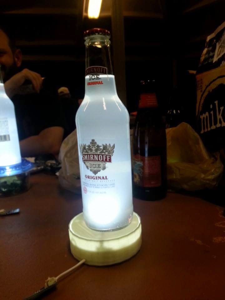
As night descended at Toxic Barbecue at DEF CON 21, everyone was working through the meat and alcohol they’d consumed much too fast and in much too large a quantity. Rather than move the party somewhere else (Las Vegas’ Sunset Park is safe at night, right?), we began to experiment with cell phone screens. The lights were bright, but they were also extremely narrow in focus.
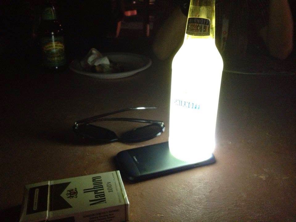
The Liter of Light project gave us an idea to use a liquid to diffuse the light. As there was still copious amounts of alcohol left behind, we started experimenting. This ‘research’ lead us to decide that Smirnoff Ice was the best diffuser. Filtered beers were awful due to both the dark bottles absorbing light as well as the liquid having no solids to scatter any that was left. Smirnoff had the clear bottle and label as well as a ton of solids from the token amount of fruit juice. As this was a hacker party and not for frat boys, we had plenty left. The uncouth among us named them ‘Bitch Lights’ after the colloquial term for Smirnoff Ice: Bitch Drinks. We had our product; now we needed to separate it from the phones.
DEF CON 22 planning started all too soon, and we needed to make good on our promises. Last year, we were too intoxicated to realize we knew nothing about how LEDs actually work. First stop? The local Hackerspace, of course. SYN Shop is in downtown Las Vegas. Multiple forum members are lighting and electronics techs on The Strip. They pointed me towards specific packages, drivers and batteries. I took this foundation and boiled it down to specifics. I wanted the light to be composed of the following elements:
- Super Bright LED (1W, 100 lumens)
- LED driving circuit
- Battery (3-4 hours of time)
- Charging circuit (USB)
- Switch to turn it on
- 3D Printed Body
Armed with search terms from the forum, I found a wealth of helpful links. I found LED packages that fit the “Super Bright” definition all over the web. I learned a ton about batteries and chargers (did you know Sears still exists and has an online store?). The most helpful site was Instructables. There, I found several LED driver circuits that I actually understood. After a trip to Frys left me bewildered with options, I learned to better read datasheets. Finally, I had a circuit plan in sight.
Design and First Prototype
I began the search for parts to fit the Instructable, and I realized I had a lot to learn about each part. To match the circuit, we searched Frys, Radio Shack, ebay, Mouser and many others online. For an unproven design, going with an unknown module and supplier wasn’t an option. Instead, we found all the components we needed on Adafruit.
- Lithium Ion batteries must be matched to their charger to avoid dangerous heat and combustion incidents. Capacity is determined by the Amp-hours rating. The LEDs I was targeting were a max of 350mAh, so I looked for batteries had to be over 1000mAh to get the targeted 3 hour run time.
- The charger choice was mostly driven by battery choice. We didn’t feel like we could provide a mounted Micro-B port in the time available, but a charging circuit mounted to a full sized USB plug was a good substitute. With the shell, we would provide an easily removable bottom and ‘mouse hole’ to allow the charger to live outside the case.
- For the LED, most LED projects online mention heat at one point or another. To get ahead of this concern, we opted for a heat sink-mounted super bright LED. This same LED bead was seen on ebay without a heat sink, but we didn’t want to screw anything up due to inexperience and opted for the more expensive package for the first run.
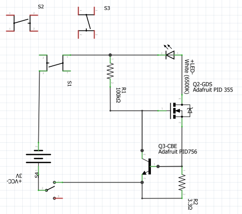
- The Driving MOSFET was a simple buy, and the choice also dictated our resistor purchase. The key value from the MOSFET we purchased was Gate Threshold Voltage. The voltage drop across R2 with the battery we bought had to match this value. Using V = IR, R = V/I = 1.5V / 350mAh ~ 4 ohms.
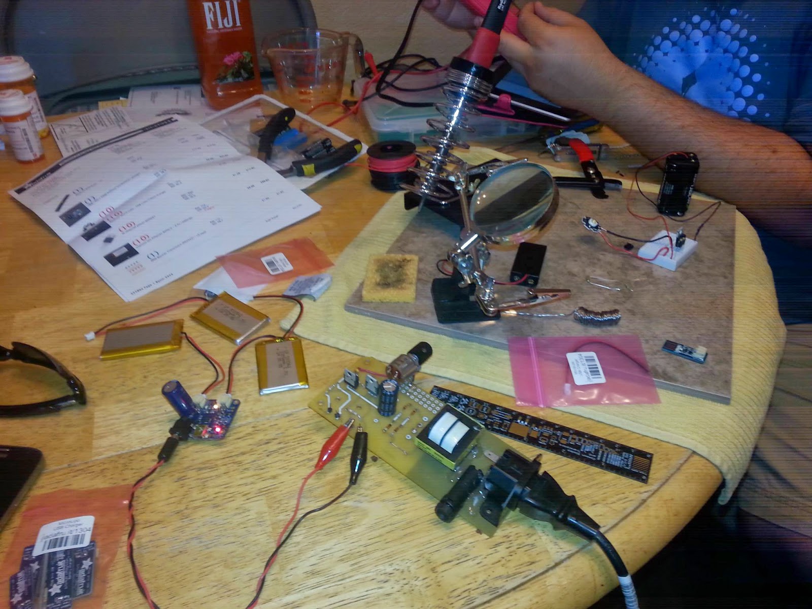
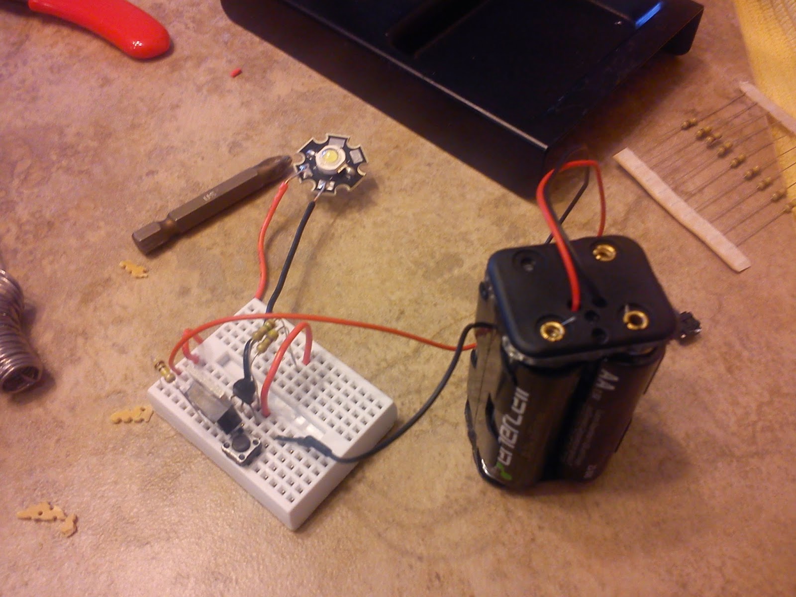
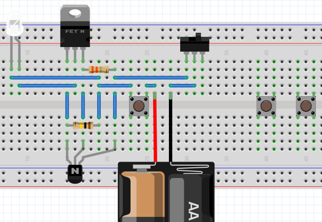
Once the materials were in hand, the breadboard went well. It worked the first time! While we waited for batteries to charge, we used a simple brick of 4xAA batteries. The beauty of the driver we chose is that it can drive LEDs using any voltage source over the target voltage.
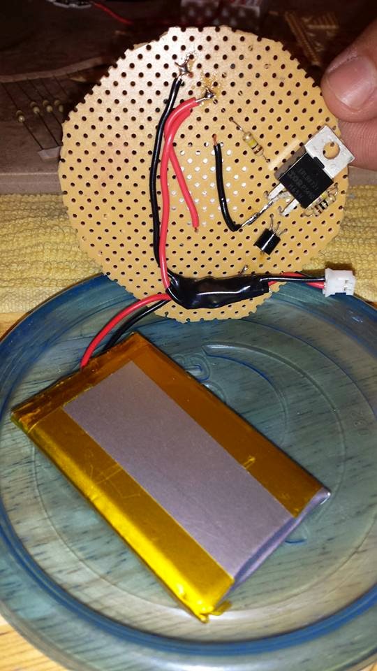
Using the breadboard and schematic, we attempted a protoboard version of the circuit. This was a complete mess, and it took us a lot longer than it should have. However, by the end of a single prototyping session, we turned a jumble of components into a working light. One high/low note happened when we wanted to minimize the number of connections but didn’t have the right resistor for R2. We twisted two resistors together to get close to R2’s 3.5 Ohms and put them through the same hole on the protoboard. Instant parallel resistor.
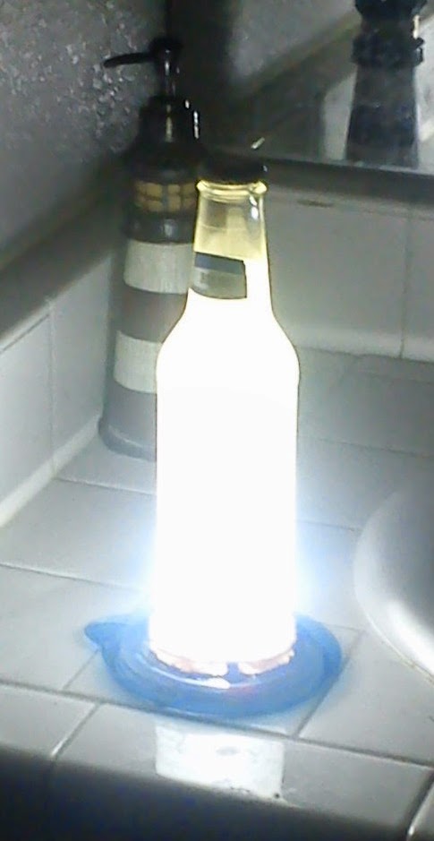
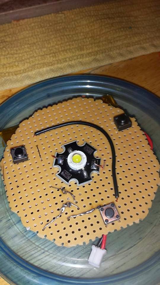
Conveniently, the whole project fit under a Ziploc Container lid. A little bit of hot glue, another section of protoboard with a hole in the middle, and charged batteries got us our first complete prototype! It was brighter than the equivalent cell phone flash and had excellent diffusion through some purpose-bought Smirnoff Ice.
PCB Fabrication
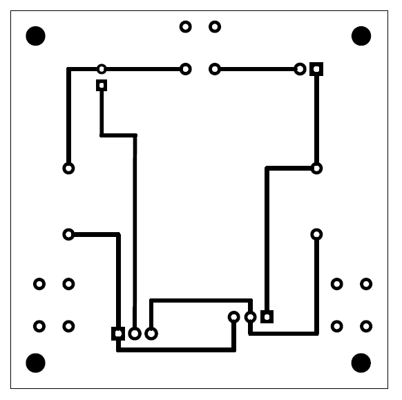
The next step along the path was to turn a gawky mess of a protoboard into an elegant example of good design. This step took a lot less time than I thought it would thanks to Fritzing. Billed as “Electronics Made Easy”, I installed and got up to speed in under an hour. Conversations with my compatriots helped me tweak and massage the design to our satisfaction. The end result is a 2” (58mm) PCB for through-hole components. This will secure the buttons, driver and LED while connecting to the battery. The experienced among you are probably thinking how absurdly large that it. It could be a lot smaller, but I consider it acceptable for a first run. As with other projects, the latest version of the fritzing file will be available on github.
If I had to pick one part of this project that made me more uncomfortable than any other, it would be the PCB fabrication steps. I took chemistry in High School and College. I know the basics. However, I don’t know enough to do it confidently. I took my queues from MAKE’s excellent video tutorial, acquired chemicals at Frys, harvested glass from a recently disabled printer/scanner, and printed transparencies at FedEx Kinkos. My exposure light was a 26W CFL in a desk lamp. My red light was a red LED straddling a button cell.
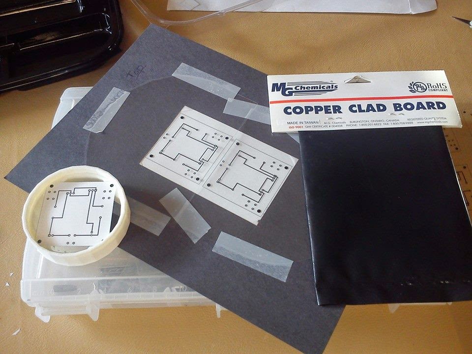
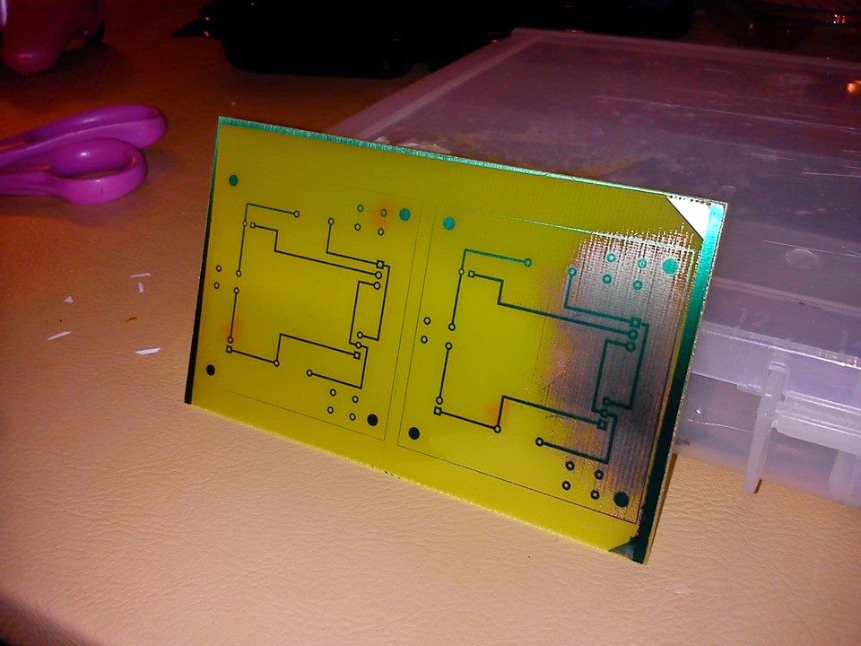
I removed the board from the developer too early or exposed it to too much light. This caused a large region of copper to not develop. There is no way to align and cut a ton of these after the fact. The PDFs exported from Fritzing come out one per page. This means they need to be done one at a time unless you have the skill to post-process the PDF into multiples per page. I pre-cut the PCB’s during subsequent runs. My table saw made short work of the big board, and the pre-sensitized copper has a sticker over it that allowed me to cut the board to pieces without compromising its ability to accept an image.
Once the etching was complete, I drilled out the traces. The prototype board was drilled using a 1/16” bit. This was way too big. Out of all the bits I tried, normall through-hole components worked great with a 1/32”. A 1/16” bit was required for the MOSFET, however. The best set I found was one for the Dremel.
The only part of the process that ended up being perilous was the disposal of the ferric chloride. The leftovers are back in the bottle. I’ll take them to the waste disposal place soon. My driveway has a nice big rust spot on it from where I washed off the etchant. How am I going to explain that to the HOA? Ultimately, the problems with Ferric Chloride lead me to a different etchant entirely: Cupric Chloride. See below.
Production Run 1
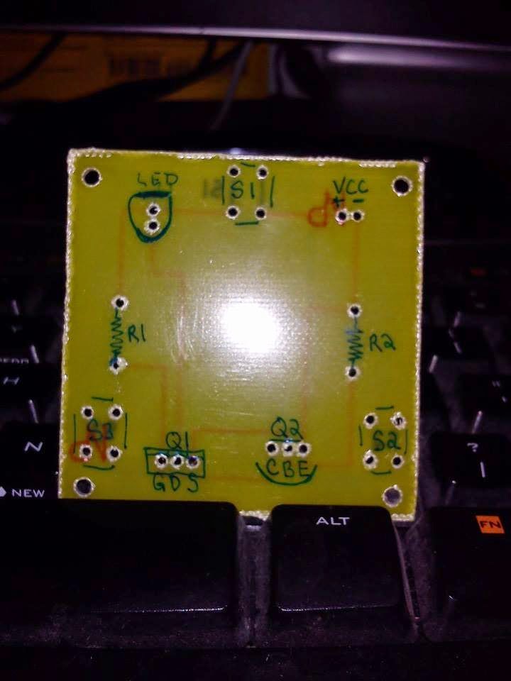
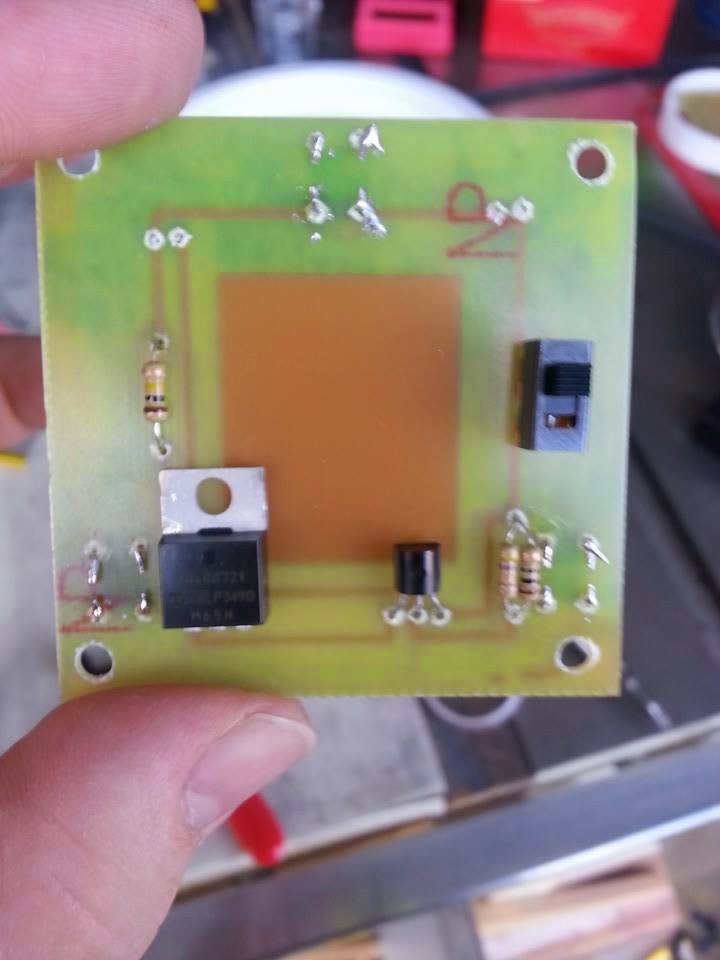
With the test run experience in hand, we were set to make an attempt at our first full run. I chopped the boards on a table saw first. This was a stunning success. I also redesigned the PCB to include a slide switch to kill the circuit. This allows long-term storage as a shifting bag or box won’t depress the pressure switches and drain the battery. You might see on the random design shots how we were planning on mounting the LED to the lid. This changed before the final production PCB run, and we moved all traces outward to make room in the center of the PCB for the LED module on heatsink. I also added a copper pad in the center to maximize heat transfer. Some thermal paste will seal the deal.
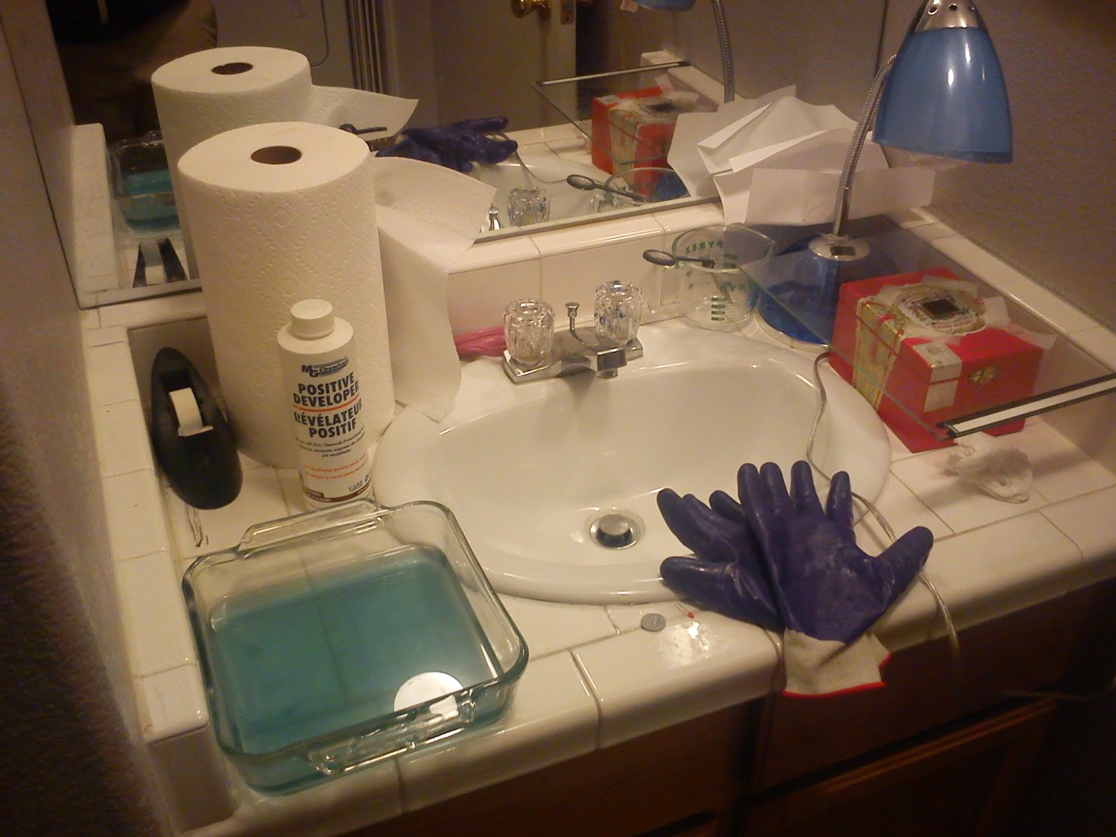
The exposure took place in the half bathroom. With access to water and no exterior windows, it was perfectly suited to etching. Our supplies were:
- Tape, transparencies and pane of glass.
- The circuit image is taped to the glass in a double-thick layer.
- Positive Developer mixed 10 to 1 in a glass pyrex. When in doubt, use pyrex to ensure things won’t melt through the container.
- Desk lamp with a sifficiently bright CFL bulb.
And our steps were:
- In darkness, peel off protective layer from light-sensitive copper clad board.
- Position the board over the top of your image and tape down.
- Flip the glass pane over and double-check the board is positioned correctly.
- Expose for 8 minutes using the lamp.
- In darkness, remove the board from the glass, and place it in the positive developer.
- Swirl the PCB in the solution until the image appears. If your developer is sufficiently diluted, longer development times will be experienced. It is better to over-develop and start to lose the image than it is to under-develop and end up with no traces at all.
- Wash off the board when it is sufficiently developed,
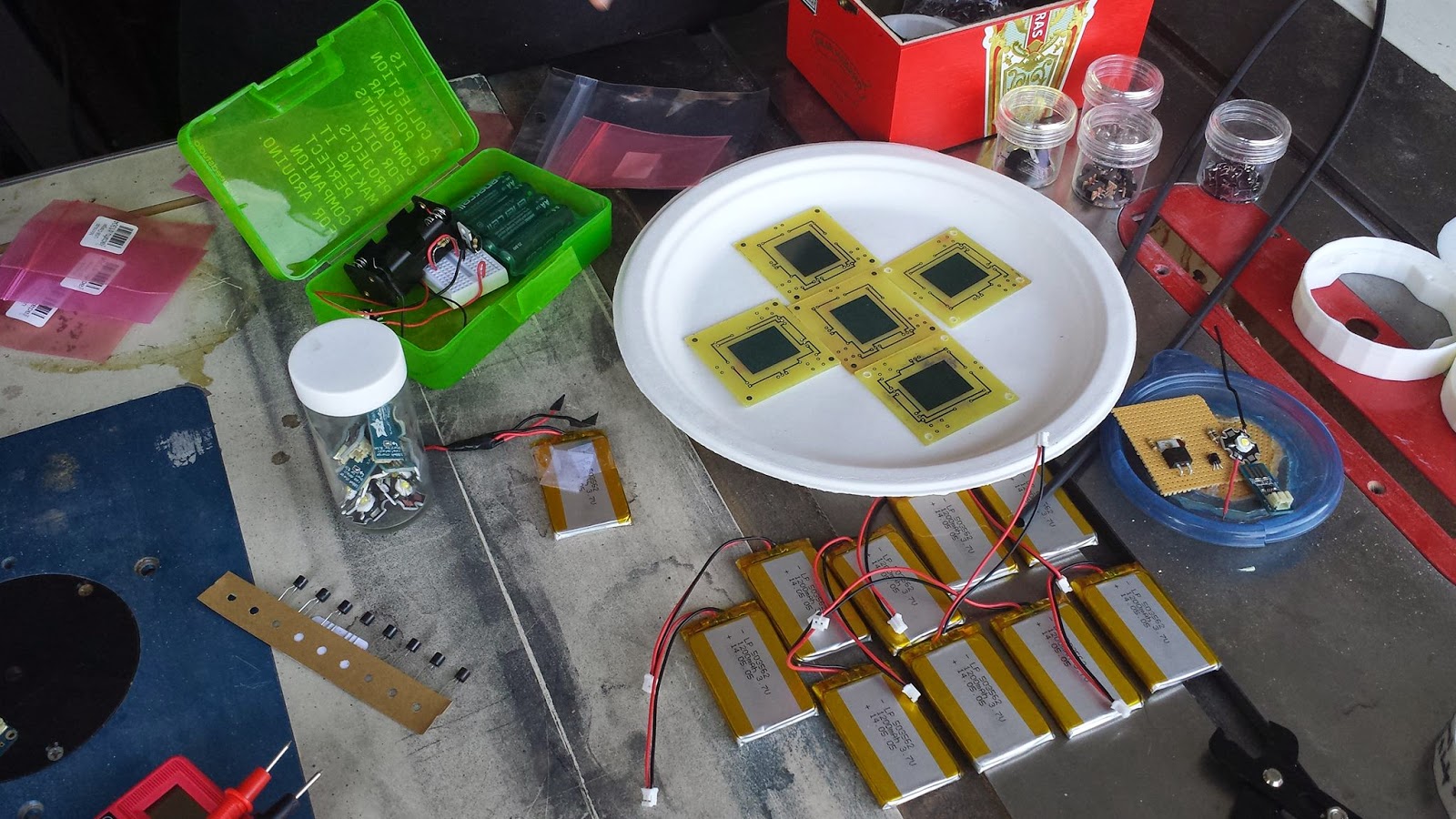
After exposure, good boards were placed into the etchant. The Ferric Chloride was a great big mess. It was hard to see how the process was coming without fully removing the board. In addition, it needs to be heated to be truly effective. Las Vegas has an ambient temperature of 100F/ 38C, and it still took 30 minutes per board. You can see the etched boards below. Before soldering, the etch-resist is removed via acetone.
Production Run 2
With DEF CON a week away, we didn’t have enough boards to complete our goal yet of nine complete lights. We met for what we thought was our last etching party. Much like the previous time, we decided to expose and etch using Ferric Chloride. These boards looked great. It was obvious we were starting to figure out how to do this effectively. Unfortunately, we also forgot to check the boards as they were produced. All 3 good boards were mirror images of what they should have been. DEF CON loomed large, and we went with the more radical solution: switch etchants and try again.
The new etchant relied on Cuperic Chloride. Once again, I turned to Instructables for a helpful tutorial. The key ingredients were muriatic acid and hydrogen peroxide. As the link shows, the acid and hydrogen peroxide oxidize the copper to form CuCl. This in turn oxidizes to form 2CuCl by stealing copper from the PCB. What’s better, it needs an acid refresh much less often, and it is completely reusable. A bubbler or aggressive mixing causes oxygen to oxidize with the 2CuCl and start the cycle again. We obtained new PCBs (see my rant about Fry’s below) and went to town. We ended up with the 9 boards we needed; we began assembly in earnest.
Lessons Learned
The first board we did had the light placed too close (1-2 inches). Also, the positive developer was extremely strong. This caused all of the etch-resistant coating to wash away. A little more water and moving the light 6-8 inches solved that problem. When we were doing it right, we waited for the image to appear and then become crisp. It is extremely difficult to tell in the dark if the image is still cloudy or not. When in doubt, dilute your developer and leave the boards in there longer.
As with woodworking, the matra is, “Measure Twice, Cut Once.” After every critical step, we had one person check another’s work. This saved us time and again from poorly aligned boards, undrilled holes and bad decisions at the bench. It didn’t save us from all screw-ups (a full crop of mirrored boards), but it saved us other embarrassments. It also exposed every team member to each point in the process. In total, five people participated in the manufacture of these boards. Most have projects lined up that take advantage of things learned along the way.
The boards themselves were a problem, and they highlighted a weakness in the supply chain. All copper obtained from Fry’s failed at least a third of the time. Online, the consensus was that the boards were old or improperly handled. The positive developer was much stronger due to being partially evaporated. The buttons we obtained were stiff and of differing quality that those used in prototypes. All in all, I would recommend avoiding Fry’s if you can help it. They might have enough materials to get you going, but Amazon or similar suppliers can get you what you need fast enough that it makes no difference.
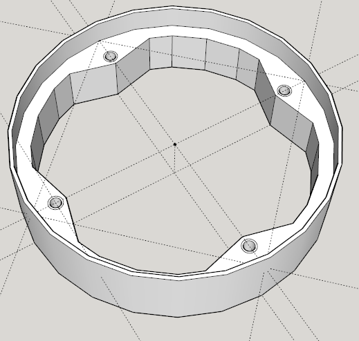
Shell Fabrication
In parallel with the circuit, we designed an enclosure that would be more sturdy than hot glue and disposable containers. The general idea was a shell with a lid that had some travel. Our first designs focused on a mechanical clip to lock the lid in place. Further ideas were a rail to keep drinks stead, a drain channel for condensation, and an interlocking base/top for easy stacking. Our lack of expertise with the 3D design software and the complexity of the print made us go back to basics.
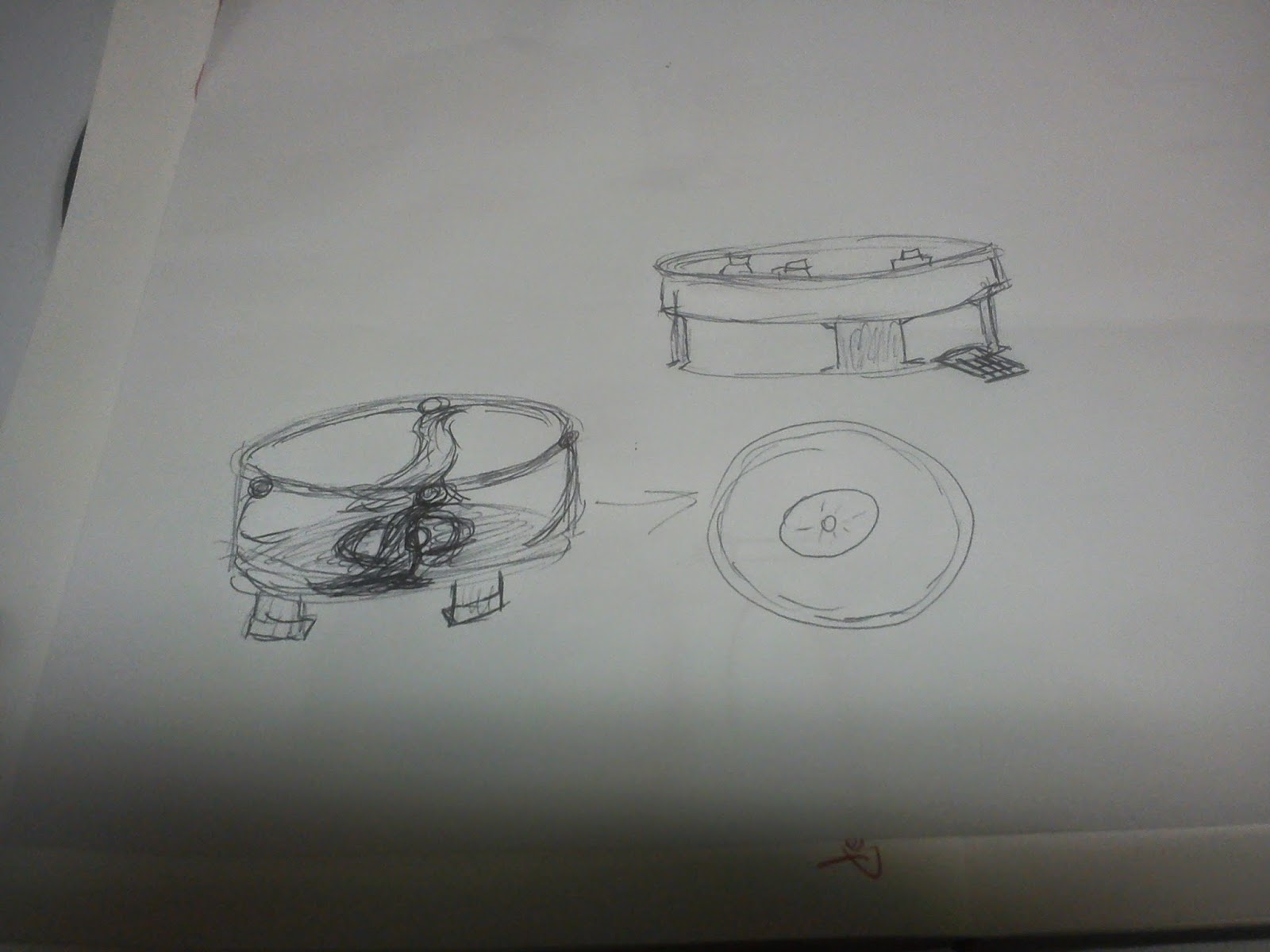
Similar products used a coaster shape, so we started there. As the whole point of this project is to show off, we wanted to make it easy to disassemble top and bottom. To make this happen, we settled on magnets instead of screws for both top and bottom.
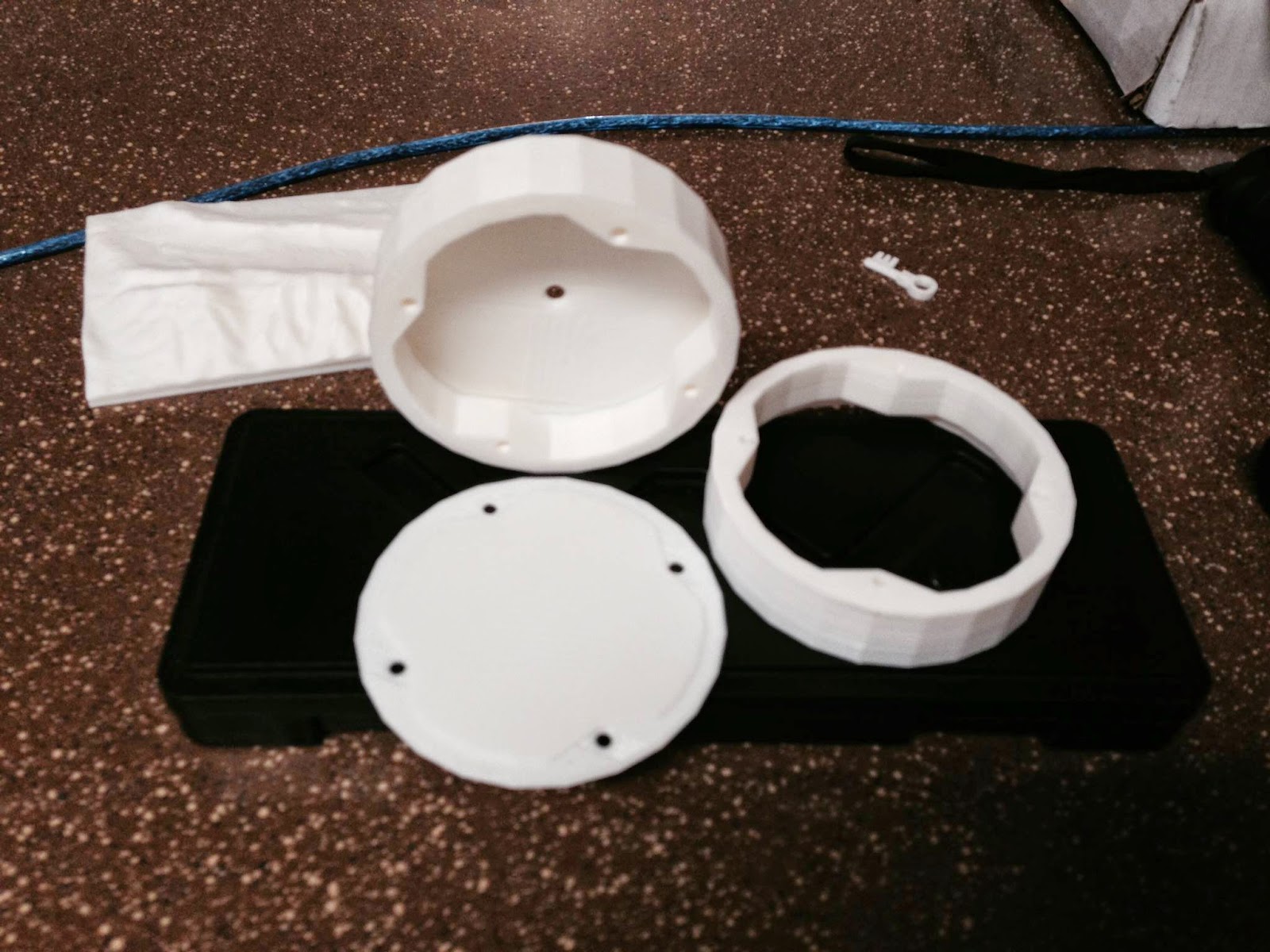
First, the 3D Printer needed to be calibrated, then the extruder needed to be cleaned, then the Kapton tape needed to be replaced. After a much better test print, we got our first dimensional fit. Once the PCB was together, we realized two things: 1) the buttons we bought had a much heavier mechanical action than the test buttons and 2) the LED package was too tall for the way we printed the top. Combine the two, and a lot less light was reaching our girly drinks. Something had to be done. The above problems were noted, and various other edits were written directly on the 3D printed shell (a sharpie on white ABS works wonders for clarity). They were handed off to our man with the printer while the rest of the team worked on PCB fabrication.
The final prototype came together the weekend before DEF CON. Edits to allow the charging cable to escape from the bottom of the case, a drip cover to prevent condensation from entering the shell, more accurately nested tops and bottoms, and a host of other small changes came together for the final prints. In all, the first run is bulkier than we imagined, but we have discussed ways to miniaturize and reduce costs across the board. It will be something we are proud of showing off.
The 3D printer was the final obstacle. From miscalibration to a clogged extruder head to a stepper motor burning out, we had our fair share of problems getting the final package in a physical format. If the repairs don’t come through, we’ll be manufacturing stand-ins for the Toxic BBQ. Nothing can stop us at this point.
The current Sketchup files will be available on the OFBC project on Github.
Putting it All Together
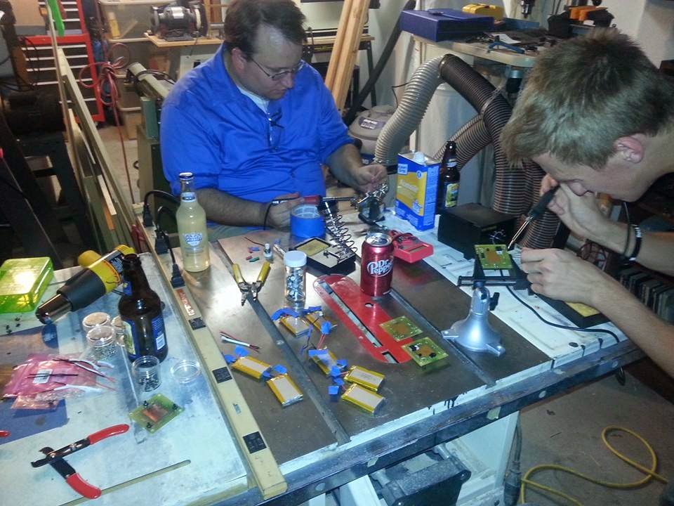
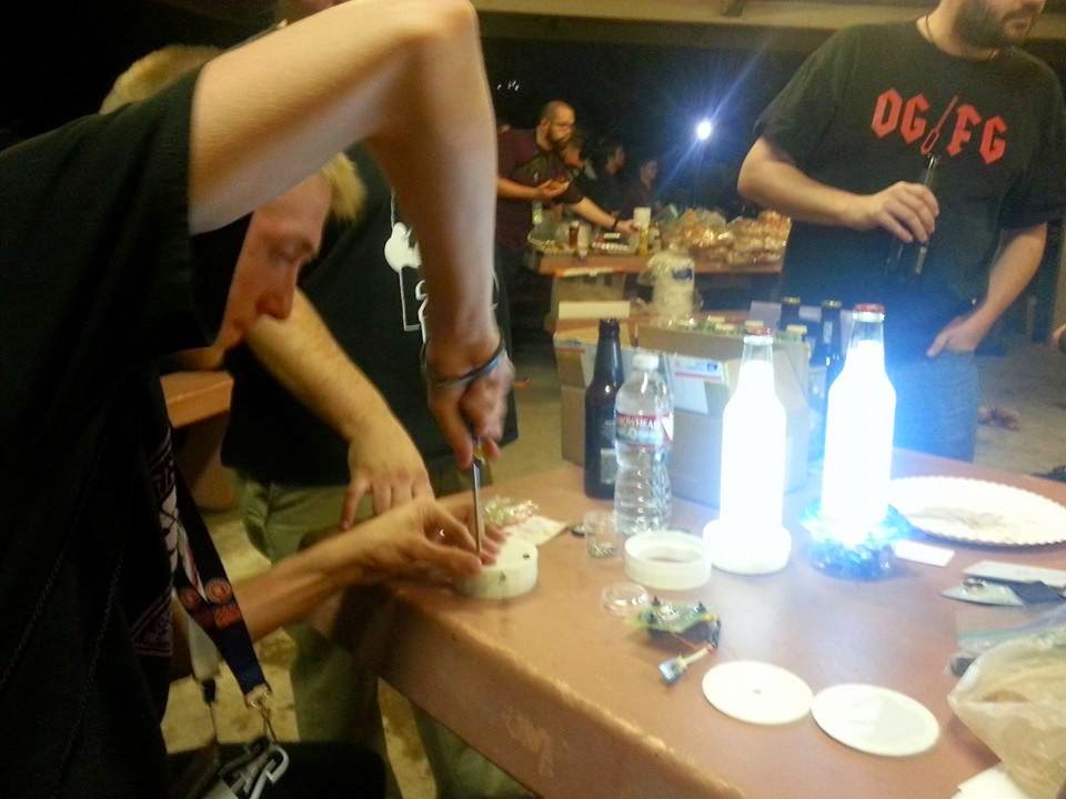
After months of effort, we had a circuit, PCB and shell design to accomplish our goal. Putting it all together meant solving some unique challenges in the home stretch. By far the most communal part of the project was finishing the circuit. Parts were bought by three different people. It took hours of trial runs and four different nights in my shop to finally get the circuit assembled and ready. In all, the project taught us to keep moving in spite of obstacles.
Internals
The main obstacle was PCB manufacture. As detailed in that post, uncooperative copper and etchant lead to abominations not fit for solder. Drill bits broke in PCBs, holes were misaligned, and traces were torn up as we worked and reworked the boards. The major blunder was the reversed PCBs, but it was tempered by the lack of polar components. Only the transistor and MOSFET needed to be adjusted when we realized our mistakes. The quality checks and encouragement as we worked as a definite plus. There were several times I wanted to just give up and abandon the project. Truly, I get by with a little help from my friends.
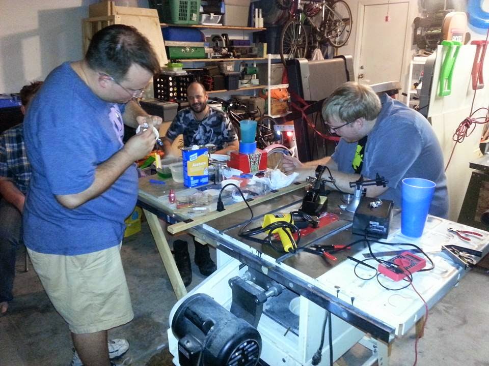
After the PCBs were in our hands, the task of soldering all the components was a team effort. One person ran continuity tests on newly etched boards. Another bridged scratches and pasted down traces. Buttons (functional and fake) were inserted and crimped at one station while a fourth person began to solder on components.
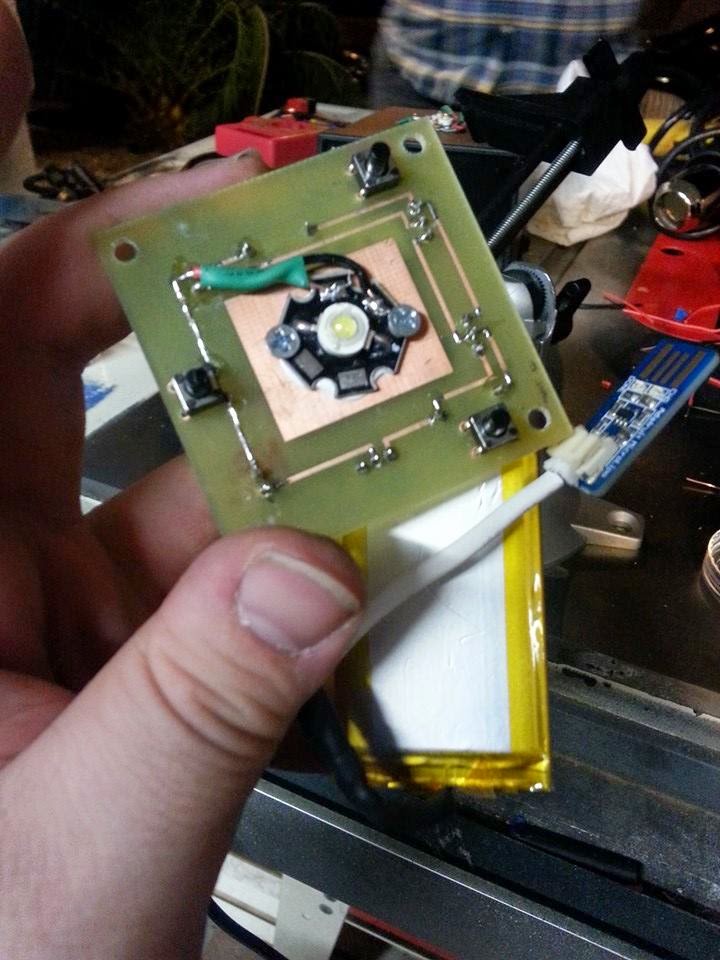
That moment of truth when the LED lit up was breathtaking all nine times it happened. When it, more often than not, didn’t work on the first try, the scramble to troubleshoot was a team effort as well. A loose connection, bad trace or through hole in need of a reflow was rooted out in minutes. I can’t describe the feelings from closing the box with nine functional copies of the idea sketched out on a picnic table the year before.
Externals
Shell manufacture forced choices between what we wanted versus what we needed. The mechanical ideas at the outset gave way to manufacturing considerations. Features were pared back to match timelines, work schedules and summer vacation. Anyone reading this who has worked in an Agile Development environment will recognize similar decisions they make every Sprint. To borrow a cliché, “Perfect is the enemy of good enough.” With this in mind, we have an eleventh hour compromise ready: should the 3D printer prove a roadblock, we have arranged for a Wednesday night Hail Mary meeting to turn Ziploc Containers into eternal glory.
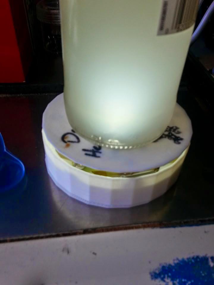
The Ziploc idea produced 4 “just in case” models. We stabilized them with glass beads and hot glue. The containers became the shell and mount for the PCB. The beverage lid was provided by another ziploc container hot-glued onto the buttons. Hot glue for grip and stabilization of the platform finished the job. See the result in the pic below next to the finished shells.
Luckily, the 3D Printer roadblock was cleared just two days before the BBQ. Poor quality filament lead to clogged extruders. After a good cleaning, we were back in business. 5 shells total were produced with various upgrades. We got a top that nested well with the shell, and the mouse-hole in the shell was added to allow the USB to be passed out of the body. We did not get impressions in the top to get the lid closer to the lens of the LED. We also did not get any part of the body held together by magnets.
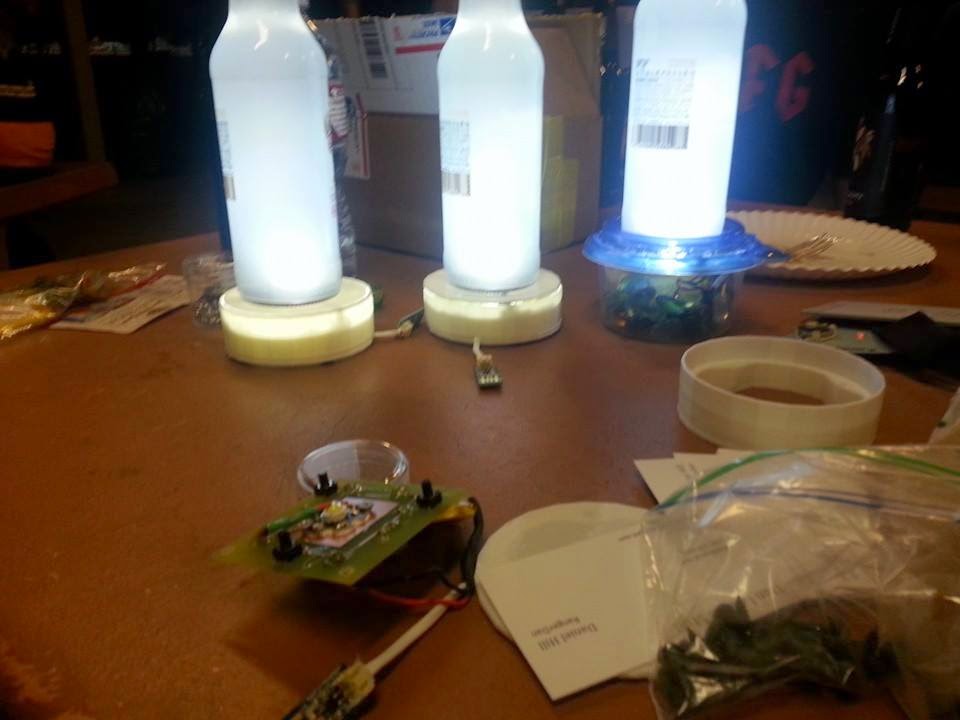
Final assembly took place at Toxic BBQ itself. The lights stayed on this year, but we started conversations and passed out some business cards with links here. We placed a few on the tables farther out that didn’t have light, and we presented two to the organizer in a Utilikilt. Furthermore, it went on display in r00tz and the HHV for most of the convention.
Final Word
I left DEF CON for two years running with a profound sense of my own shortcomings. I saw people around me doing amazing things, but I couldn’t point to similar achievements for myself. Though not terribly complex (most ideas came from Instructables, after all), the process and coordination required to pull off this simple idea has been eye opening. It all started by pivoting from planning to doing. It finished with an 80’s-montage-worthy string of late nights and high fives.
Already, these efforts are fertile ground from which numerous other ideas have sprung. Facing another DEF CON, I’m looking for the next big project instead of lamenting my noob credentials. Only time will tell how many of these work their way to reality.
The Team
- Producer and Assembler: The_Bozo
- Project Manager and Circuit Design: DuncanYoudaho
- Circuit Troubleshooting: GlassyRye
- 3D Models and Printing: Fox
- Intern: [Name Forgotten]
Github: https://github.com/RangerDan/OneFluorescentBeerCoaster
Acknowledgements
- Gravedigger for hosting Toxic BBQ
- SYN Shop Forum members for the LED Driver advice that got us going
- Instructables for their wonderful platform that allows the sharing of such diverse information
- Adafruit for having all the parts in one place
- Bloodhound Gang for the product name